Vertical TV CATV Distribution Diagram for Dual High Rise Towers DWG
Description
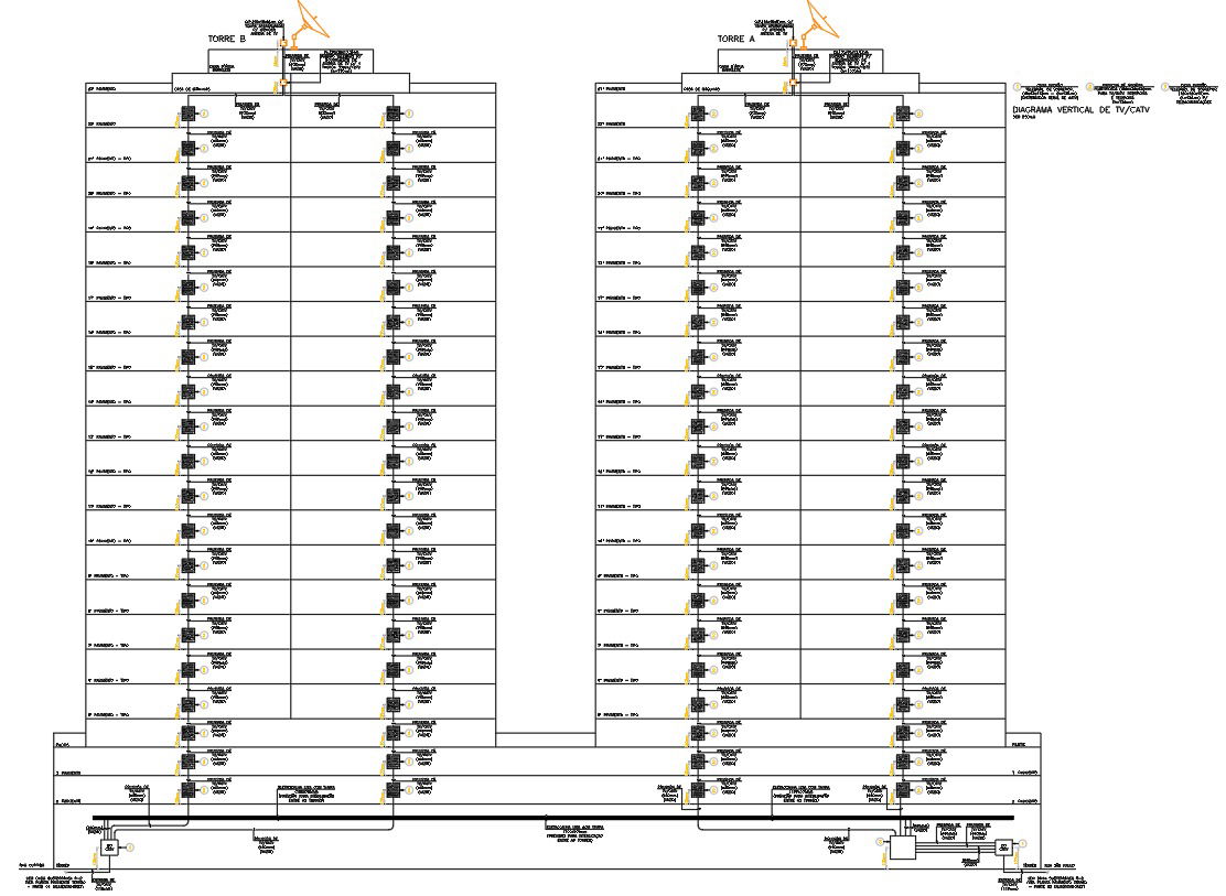
This detailed AutoCAD DWG file presents a complete vertical TV and CATV distribution diagram designed for two multi-storey residential towers labeled Tower A and Tower B. The schematic illustrates floor-wise signal routing from rooftop antenna systems and satellite receivers down through each residential level. Each floor is equipped with clearly marked TV outlet points, coaxial cable routes, distribution boxes, and signal amplifiers to ensure seamless media transmission. The drawing also highlights vertical risers, junctions, and inter-tower connectivity pathways essential for consistent and balanced CATV distribution in high-rise buildings.
The diagram further includes accurately detailed components such as network splitters, grounding units, line amplifiers, and main distribution frames positioned at the lower level of the building. All cable routes and system nodes are precisely represented with clean technical linework and structured annotations. This DWG file is suitable for electrical engineers, structured cabling designers, and communication system planners involved in residential tower infrastructure. It is ideal for project documentation, system maintenance, signal planning, and installation coordination within large residential developments.
File Type:
DWG
File Size:
470 KB
Category::
Electrical
Sub Category::
Electrical Automation Systems
type:
Gold

Uploaded by:
Eiz
Luna
